Trip point and time delay characteristics of Heinemann hydraulic-magnetic circuit breakers are sensitive to changes in frequency, so they should only be used on the frequency for which they were calibrated.
If a Heinemann hydraulic-magnetic circuit breaker is used in a circuit with a frequency different from that for which it was calibrated, it will not perform according to the catalog specifications.
Use of a DC breaker in an AC circuit will often produce a nuisance-tripping failure, thus rendering the load unusable; an AC breaker installed in a DC circuit may fail to trip when necessary, and thus will not be protecting the load.
Similarly, an AC circuit operating at a frequency other than 50/60Hz (such as 400Hz, which is often used in aircraft) will require that the circuit breaker protecting it be calibrated to operate at that particular frequency.
Some models of Heinemann circuit breakers can be calibrated for use in multi-frequency applications, but these units are given a wider range of tolerance on the trip point – which will often require that conductors and other devices in the circuit be sized larger to
accommodate the higher current levels which may be required to cause the breaker to trip.
There are two things to watch out for.
1. Heat generation. You need to make sure there is adequate space for ventilation, especially if you intend to run close to the must-hold rating or in a high ambient temperature environment (ie. close to the +85°C limit inside the enclosure).
2. Mounting dimensions. Add about 0.005” – 0.010” [~0.15-0.25mm] to the nominal breaker width for spacing the mounting holes. The thicknesses of the adhesive labels on the sides of the breakers adds a little to their width, and although it does not mean much for a breaker mounted by itself, it can add up quickly when many are flush-mounted in a row. Mounting them on a centre-to- centre spacing precisely equal to their nominal width could leave you with unusable positions along the row because of how the accumulating error could
misalign the mounting holes.
Standard auxiliary switch terminals are quick-connect type in the following sizes:
For GH, GJ, and GJ1P:
0.187” x 0.020”
For AM-series, C-series, and J-series
0.110” x 0.020” (Standard)
0.187” x 0.020” (On special order)
Yes, on certain models as listed below. A special catalog number is required, and there is
usually a substantial price increase.
C-series: #6-32 screws or #10-32 studs
GH: #6-32 screws
GJ1P: #6-32 screws or #10-32 studs
GJ: #6-32 screws or #10-32 studs
These constructions usually also require substantial change to the external dimensions of
the product; consult the factory for details.
Please do not attempt to seal the vent openings on Heinemann circuit breaker
products. These openings are provided for the expulsion of ionized gases
produced in the arc chamber – failure to vent these gases quickly could cause an
explosion.
If it is necessary to use a Heinemann circuit breaker in a high-contamination
environment, an environmentally sealed enclosure should be used. The circuit
breaker may then be mounted such that its operating handle protrudes through
the front of the enclosure, thus eliminating the need to open the enclosure in
order to operate the breaker. Sealing around the handle is then accomplished by
means of a silicone-rubber boot, available from Heinemann as an accessory
component.
Please ensure that all applicable building and electrical code requirements are
observed in the installation.
Some inductive loads draw a brief high-magnitude initial transient surge as part of
normal operation. While such a high surge presents no danger to the circuitry, it can – if
the magnitude is high enough – trip the breaker. Heinemann standard series trip
constructions will tolerate such a surge up to 8 times the nominal amp rating for the first
½-cycle pulse (8-10 milliseconds on DC); if the surge exceeds this value, the breaker may
trip – thus needlessly preventing normal startup of the equipment.
Since inductive-load circuits are normally designed so that this brief surge will not
damage the equipment, it is sometimes necessary to modify the circuit breaker such that
it will tolerate this high-magnitude surge long enough to allow the equipment to start, but
not long enough to permit damage. The high-inrush tolerance feature available for
Heinemann hydraulic-magnetic circuit breakers allows much higher surges (18x for
AM/JA; 25x for CD/GH/GJ) to pass without tripping the breaker, while still providing
normal time-delay overload protection at lower overload levels.
The handles can physically be tied together such that they may be manually
switched in unison, but doing so is not recommended because such a
combination can create a hazardous condition because it will not function as a 2-
pole unit. If an application requires a multipole device, then it is a multipole
device that should be installed in it.
Heinemann circuit breakers are the “trip-free” type: the internal mechanism will
operate on overload, and separate the contacts even if the handle is forcibly held
in the “ON” position. The handle-return mechanism is designed only to gently
return the handle to the “OFF” position in order to reset the device once the
tripping action is completed, and does not have sufficient strength to turn off any
adjacent breaker to which it may have been joined. Heinemann multipole
devices incorporate an internal mechanism that enables one pole to trip the
other(s) without requiring movement of the handle. If two adjacent single-pole
devices are joined by their handles, this is how they will behave when an
overload condition occurs:
1. Both units will sense the overload, and begin to respond.
2. One unit will complete the tripping action before the other, thus
interrupting the flow of current.
3. With the flow of current interrupted, the other unit will not complete its
tripping action.
4. Both handles will remain in the “ON” position, and thus it will not be
evident which, if any, breaker has tripped.
5. The load will cease operation in a manner that clearly indicates energy
flow has stopped; but some conductors will remain energized.
6. A hidden – and possibly lethal – electrical shock hazard could then exist for
technicians attempting to restore the load to proper operation.
This kind of problem is known as “nuisance tripping”. While it is frequently
blamed on (and sometimes caused by) a defective circuit breaker, there are
other possible causes that should be ruled out before returning the breaker to the
factory. Here are a few simple things that should be checked before replacing
the breaker:
1. What is the actual load on the circuit? This can be checked fairly easily
with an ammeter. Sometimes the current drawn in the circuit is more than
expected, and may even exceed the rating of the breaker. In this
instance, the breaker detects an overload condition, and acts to
disconnect the power as intended. If such a load is actually normal, and
the wiring is sized to accommodate it, the breaker should actually have a
higher trip rating.
2. How is the breaker mounted? Heinemann circuit breakers are gravity-
sensitive, and should be mounted in their intended orientation, usually on
a vertical surface. Rotating the device to operate in a table top or ceiling
orientation will alter its trip point, which may create nuisance tripping.
3. What kind of load is the breaker protecting? Inductive loads such as
transformers and motors can draw start-up spikes high enough to trip the
breaker, even though the normal steady-state load is well below the
breaker rating. A special calibration is sometimes required for breakers
protecting this type of equipment.
4. Is the equipment vibrating? Portable equipment, such as vehicles or
mobile generators, can be subject to vibration conditions. Heinemann
circuit breakers are built to meet the requirements of MIL-STD-202 with
respect to shock and vibration, but if the levels anticipated in this standard
are exceeded, the vibration could be enough to make the breaker trip.
A “general purpose” circuit breaker is one that is suitable for use in any electrical installation
where its rating matches that of the circuit it is protecting. (The breakers in your house are
probably “general purpose”.) A “special purpose” circuit breaker is one that can only be used in
certain applications because it has certain features or characteristics that may make it fail to
properly protect the circuit if installed in an incompatible application. The “special purpose”
designation is a reminder to check that the circuit breaker in question is really the one specified
for that application, and to exercise caution when installing it.
The main issue here is the terminations. When a circuit breaker has optional features (eg.
auxiliary contacts, remote trip coils, mixed ratings, etc.) there is a risk of incorrect installation. If
the application is not designed to accommodate these functions, their terminations may interfere
with mounting brackets etc. in the panel, creating hazards from poor power connections or
exposed live parts. Or connections may be mistakenly be made to the incorrect terminals, with
the result that the device does not protect the circuit. But if the circuit breaker has the features
and functions required for the application, and the application is designed to accommodate that
circuit breaker with those features and functions, then there will be no problem using it.
The “special purpose not for general use” marking is there as a warning for electricians to
exercise caution when installing replacement circuit breakers or when attempting to re-
commission units recovered from retired applications.
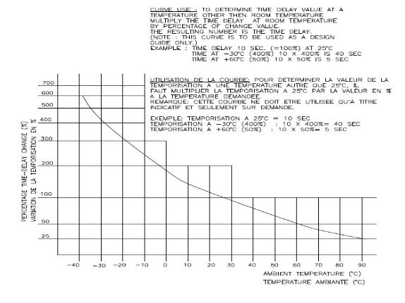
Unlike thermal devices, the trip point of a Heinemann magnetic-hydraulic circuit
breaker is unaffected by changes in the ambient temperature. This type product
can therefore be used in any application where the ambient temperature remains
within the circuit breaker’s operating range of -40°C to +85°C.
The time delay, however, is affected such that at higher temperatures trip time is
reduced and at lower temperatures it is increased. Please note that the graph
below is only to be used as a guideline for design purposes, and is not intended
as specifications for product conformity testing.
The following torques are recommended for Heinemann circuit breaker products:
| Product | Mounting Threads | Terminal Threads |
| Size | Optimum | Max | Size | Optimum | Max | |
| J-series | 6-32 | 5-7 | 10 | 10-32 | 7-9 | 10 |
| 1/8-32 | 15-20 | 22 | 8-32 | 7-9 | 10 | |
| 1/2-32 | 20-25 | 26 | ||||
| 009-18056 (Terminal Adaptor) |
6-32 | 3-5 | 5 | |||
| AM-series | 6-32 | 5-7 | 10 | 1/4-20 | 30-35 | 35 |
| 10-32 | 15-20 | 20 | ||||
| C-series | 6-32 | 5-7 | 10 | 1/4-20 | 30-35 | 35 |
| 10-32 | 15-20 | 20 | ||||
| GH | 8-32 | 7-9 | 10 | 1/4-20 | 50-60 | 75 |
| GJ | 10-32 | 15-20 | 20 | 3/8-16 | 100-130 | 130 |
| 5/16-18 | 60-70 | 70 |
For pressure-connector style terminals:
| Product | Wire Size | Tightening Torque |
| GH / C-series | 14-10 AWG | 35 |
| 8 | 40 | |
| 6-4 | 45 | |
| 3-1/0 | 50 | |
| GJ/GJ1P | 6 AWG-250 MCM | 275 |
All torque values are given in in-lb.
A Heinemann hydraulic-magnetic circuit breaker may be tested by applying a current
greater than its nominal rating, and then measuring the time required for it to trip.
Trip tests for quality evaluation of Heinemann hydraulic-magnetic circuit breakers
should be performed at the lowest level of current at which the device must trip – 125%
of nominal rating for most construction types. A low voltage should also be used, to
avoid unnecessary wear on the contacts. This is a meaningful test that will consistently
distinguish a good product from a defective one because the magnet is then in its
weakest condition. This is the test used in the factory to evaluate finished products.
Testing at higher current levels will reduce the time required to perform the test, but it
will also reduce the relevance of the test results. Such tests at overload levels beyond
200% are not recommended; the trip times at these high levels vary greatly even
between individual identical products because, under those conditions, the magnet can
then become strong enough to overcome the time delay mechanism before it completes
its cycle.
Trip time ranges are given in the catalogs for higher overload levels, but these values
are not intended as specifications for product conformity testing. They are statistical
limits for the product design overall, and are provided as a guide to circuit designers for
what to expect for the behaviour of the product type in general. Individual products are
not considered defective if their trip times at overloads beyond 200% fall outside the
ranges given.